During the programming process of the impeller using the UG impeller machining module, it was found that the impeller blade top surface boundary was not designed chamfered. This paper discusses the problem, analyzes the possible causes of the phenomenon, and proposes several solutions.
1. The discovery of the problem
Our company needs to process a batch of titanium alloy impellers. When programming the impeller, the UG impeller machining module is used, and simulation software is used for simulation. There is no over-cut alarm during the simulation. However, in order to ensure the quality of the processing, the aluminum alloy is first used for trial cutting to verify the program. When the first blade was finished, it was found that the top surface of the blade showed a sharp chamfer, as shown in Fig. 1. However, there is no chamfer on the 3D model, as shown in Figure 2, indicating that overcutting occurred during processing. The machined parts do not match the model and need to be analyzed and resolved.
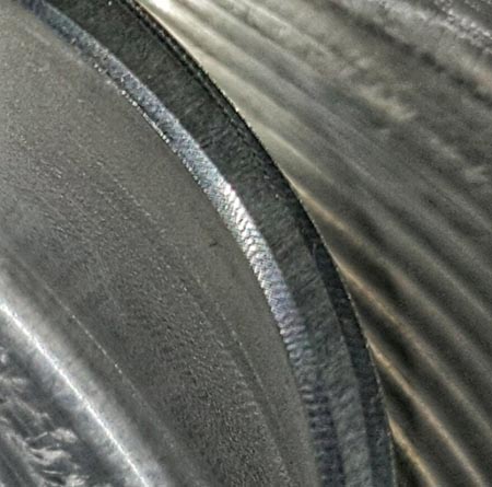
Figure 1 The top of the blade appears to have a chamfer

Figure 2: There is no chamfer on the top of the blade in the model
2. Problem analysis
Firstly, the blade finishing tool path shown in Fig. 3 is analyzed. After careful observation, it is found that there are some tool paths near the top of the blade by the tool path generated by the impeller module, as shown in Fig. 4, it can be sure that it is generated with chamfering. related. However, there was no over-cutting hint during the simulation. Through the analysis of the impeller pattern, it was found that the impeller coating surface of the transition blank in Figure 5 is a positive tolerance, that is, the impeller blank coating surface is larger than the impeller model, so There was no overcut during the simulation, but the actual machining was too cut.
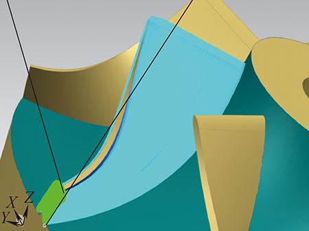
Figure 3 Blade finishing tool rail
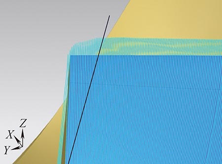
Figure 4 Blade top surface rail
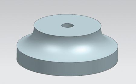
Figure 5 Transition blank
Comparing the previously completed impeller test piece, it was found that there was no undesigned chamfer on the top of the blade. The tool path for machining the impeller blades before was generated by the “variable contour milling†function in UG, and the tool path is shown in Fig. 6. Comparing the two tool paths, it can be clearly observed that the tool path generated by the variable profile milling does not have the extra tool rail at the top of the blade, which is one reason why the top surface of the previously processed impeller blade is not chamfered. Another reason is that the impeller coating surface of the transition blank used in the previous processing has a negative tolerance, so that chamfering due to overcutting does not occur. Even if there are positive tolerances in the previously processed transition blanks, machining the blades with variable profile milling may result in a very small portion of the top of the blade being unmachined, but without chamfering.
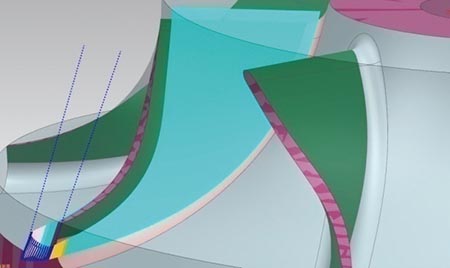
Figure 6 Variable Contour Milling Path
Based on the above analysis, the appearance of the non-designed chamfer at the top of the blade should be caused by the combination of the “excessive†tool path at the top of the blade and the positive tolerance of the transition blank impeller.
3. Problem solution
According to the requirements of the drawings, the impeller coating surface has a positive tolerance within the tolerance range, so the impeller transition blank after turning is qualified, the blank cannot be changed, and the problem can only be solved by programming. Using a multi-axis module as described above avoids machining chamfers, but the programming effort is large. Now we will focus on how to properly set the impeller processing module to generate a machining program that meets the requirements.
Since the appearance of the chamfer on the top surface of the blade is related to the uppermost tool path, first consider how to remove the uppermost tool path. Adjust the cutting path setting and remove the uppermost cutting path to avoid the occurrence of chamfering. As shown in Figure 7, you can set the "starting %" in the "tool path setting" → "cutting layer". When the setting "starting %" is 5 and other settings are unchanged, the generated tool path is as shown in Fig. 8. Show. It can be observed from the figure that the tool path near the top of the blade is eliminated, and in theory the formation of the top chamfer can be avoided. However, this method may encounter problems in practical applications, that is, how to set the "starting %" reasonably, the value setting is too small may not achieve the purpose of eliminating the chamfering, and the setting of the over-assembly may make the top part of the blade unable to It is processed.
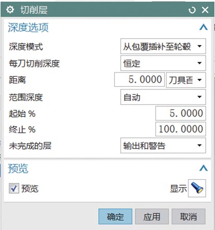
Figure 7 sets the cutting "starting %"
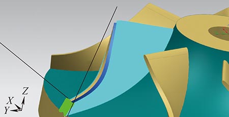
Figure 8 Set the tool path generated after the "starting %" is 5
In addition, it is necessary to consider changing the impeller model to match the turned blank. However, the size of the cladding surface is difficult to measure accurately. After analysis, the cladding surface of the impeller model can be made larger, which is equivalent to extending the blade to the cladding surface. The blade extension size should not be too large. If the production efficiency is reduced, it cannot be If it is too small, it will still have a chamfered cut. It should be extended according to the maximum tolerance of the pattern. In addition, the influence of other factors such as positioning should be increased by 0.5mm. The extension effect is shown in Figure 9.
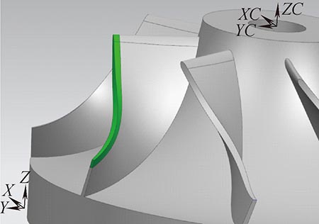
Figure 9 extended blade height
According to the above analysis, the impeller model and the toolpath parameters were changed, and the impeller module was used to generate the blade finishing program, the simulation was performed, and the remaining blades were processed. As shown in Fig. 10, no chamfering occurred.
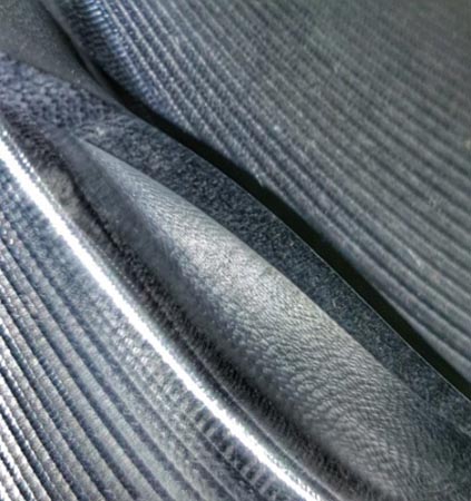
Figure 10 No chamfering on the top surface of the blade
4. Conclusion
In this paper, the problem of programming the machining impeller using UG impeller module is analyzed, and the solution is proposed. It is proved that the impeller machining module can efficiently generate the impeller machining program, but it should be noted that when using the impeller machining module to generate the tool path, it is necessary to The actual situation can be corrected by modifying the 3D model and the toolpath parameters to create an ideal tool path. The discovery and solution of this problem on the other hand reflects the necessity of trial processing before using new methods to process new products. Through the processing of test pieces, various problems can be found in time, and debugging can be improved for the problem. To the extent that economic losses caused by similar problems in the formal processing process are avoided.
references:
[1] Xing Jishou, Wang Hongzhi, Yang Qingdong. Research on Five-axis NC Machining of Integral Impeller[J]. Mechanical Design and Manufacturing, 2013(8): 155-157.
high pressure gun ,trigger gun ,unload valve,bypass valve,regulator valve, high pressure hose, gauge,spray nozzle
The spare parts & accessories service is necessary to the trouble-free experience in using triplex plunger pumps, we have the complete list of spares for your repair & maintenance with affordable pricing, fair-enough.
You can select the original spares from us, including varieties of parts, such as ceramic plungers, seal kits, crankshafts, bearings, delivery valves, o-rings.
High Pressure Gun,Trigger Gun,Unload Valve,Bypass Valve,Regulator Valve,High Pressure Hose,Spray Nozzle
Zhejiang Botuolini Machinery Co.,Ltd , https://www.chinaplungerpump.com
