Distributed power stations are different from large ground power stations. Distributed power stations are generally built on the roof of industrial and commercial enterprises. Most commercial and commercial roofs will also have other equipment. For example: central air conditioning cooling towers, general air conditioning compressors, elevator shafts. At the same time, the surrounding tall buildings and trees will affect the shadow of the rooftop distributed power station at a specific moment; leaves and bird droppings will adhere to the surface of the battery assembly. Air conditioning systems can cause local array heating systems to heat up. Due to the above complex factors, the impact of these factors on the power generation system must be analyzed.
1.1 Hot Spot Effects and Mathematical Models
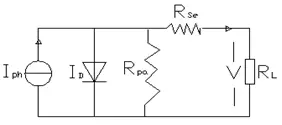
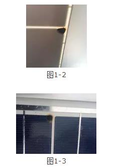
The hot-spot effect refers to a normal working battery assembly at a certain time, a single cell sheet is covered by a small object. As a result, the current generated by this single cell cell becomes smaller. The unit cell in the battery pack can be seen as a PN junction structure with similar diodes, with reverse avalanche breakdown, according to Kirchhoff's current and voltage law, when the blocked single cells can produce When the current is less than the current of the circuit, the cell has a negative pressure and becomes a load. And in the form of heat to consume the energy of other monomer cells.
Picture 1-1
IPH=I+Id+Ipa+Ise(1-1)
As shown in equation (1-1), when the battery module is operating normally, the photocurrent IPH is consumed by the three links, part of which is consumed by the load (I), part of which is consumed by the internal resistance (Ipa+Ise), and part of which is equivalent to the diode. Depletion (Id) When the hot spot phenomenon occurs, the values ​​of Ipa, Ise, and Id become large. When the three are superimposed to reach a certain value, the cell will be broken. The hot spot effect is also closely related to the production process of the battery module. Due to the defect of the production level, the internal resistance of the cell is often uneven. Non-uniform internal resistance of the battery can easily produce hot spots.
The hot spot effect is very harmful. If it is light, the battery is burned, which can cause serious burning of the entire battery assembly and cause a fire. In recent years, power station fires caused by the hot spot effect have occurred. A fire in a distributed power station will not only result in property damage, but also cause serious casualties. This requires that the power station management regularly inspects and cleans in a timely manner to avoid danger.
2 Influence of environmental factors on battery components
1.2.1 STC Standard Test Conditions
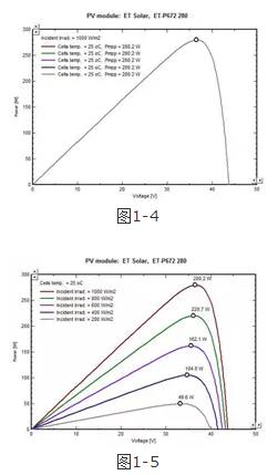
The STC (Standard Test Condition) test is a standard test. The basic principle is that when the flash shines on the battery under test, the current change in the solar battery is controlled by the electronic load, the voltage and current on the volt-ampere characteristic curve of the battery, the temperature and the radiation intensity of the light are measured, and the test data is sent to the microcomputer. Process and display. International peer standard test environment: irradiance 1000W/M2, ambient temperature 25°C, AM=1.5; power tolerance range: ±3%. As shown in Figure 1-4, a manufacturer model is ET-M672280WW280Wp battery module in STC Environmental PU curve. (This chapter uses this type of battery assembly as an experiment and simulation object)
1.2.2 Effect of Shading on Battery Components
The direct influence of the large shadows produced by clouds, tall buildings, and trees on the battery components is the change in solar irradiance. The curves in Figure 1-4 were generated at a irradiance of 1000 W/M2. Figure 1-5 shows the PU curves and maximum power point data for five different irradiance conditions. See Table 1-1
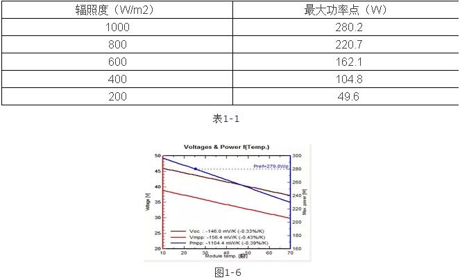
As shown in the data in Table 1-1, the greater the irradiance, the greater the output power of the component, and vice versa.
1.2.3 Influence of Temperature on Battery Components
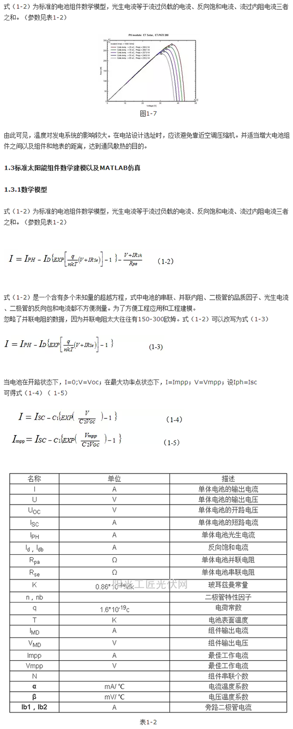
The solar cell module has two parameters related to temperature, namely voltage temperature coefficient and current temperature coefficient. The open circuit voltage temperature coefficient of the ET-M672280WW battery pack is -0.33%/K. That is, when the temperature rises by one Kelvin, the open circuit voltage of the module will drop by 0.33%, about 146mV, and vice versa. The short-circuit current temperature coefficient of the battery module is 0.031%/K. When the temperature rises by one Kelvin, the short-circuit current of the module will increase by 0.031%, which is about 2.49mV, and vice versa. The voltage and current changes caused by the temperature rise are smaller due to the current change. As shown in Figure 1-6, the temperature has a relatively large influence on the power of the module. For each Kelvin temperature increase, the output power of the battery module drops by 0.39% to approximately 1.1W. Figure 1-7 generates data, temperature rises 10-11W every 10K.
This shows that the temperature has a greater impact on the power generation system. In the site design of the power station, close to the air conditioning compressor should be avoided. And properly increase the distance between the components of the battery and between the components and the surface to achieve the purpose of ventilation and heat dissipation.
1.3 Standard Solar Module Mathematical Modeling and MATLAB Simulation
1.3.1 Mathematical model
1.3.2 MATLAB Engineering Modeling
After the MATLAB engineering modeling by equations (1-3)-(1-12), the internal correlation of the battery components is shown in Figure 1-8.
After the internal correlation structure is encapsulated, parameters are set, as shown in Figure 1-9. Components such as open circuit voltage, short circuit current, optimal operating voltage, current, voltage, current temperature coefficient, temperature, solar irradiance and other parameters can be freely set.
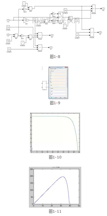
Figure 1-10 shows the UI curves obtained under the STC conditions after the MATLAB model is simulated; Figure 1-11 shows the PU curves generated by the MATLAB model under conditions of irradiance of 800W/M2 and temperature of 45 degrees Celsius; Figure 1-12 shows the spokes. The PU curve generated by the Pvsyst software under conditions of illumination of 800W/M2 and temperature of 45 degrees Celsius. Figure 1-13 is a PT simulation diagram under MPPT. (perturbation observation method)
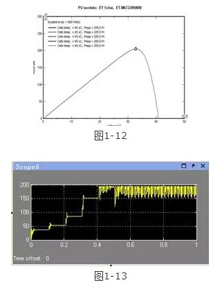
It can be seen from the figure that the data simulated by MATLAB and Pvsyst software has a difference of 1-2%, indicating that the MATLAB battery component model derived from the mathematical model can be completely used for engineering simulation.
1.4 Distributed Power Plant MATLAB Simulation in Complex Environment
Most of the distributed power stations are limited by the roof area and have little installed capacity. At the same time, due to the size of the power distribution room, there is no way to use a bulky centralized inverter. Outdoor multi-channel MPPT string inverters are often used. At present, the power of the string inverter is between 10KW-50KW, which can be flexibly configured according to the installed capacity of the power station.
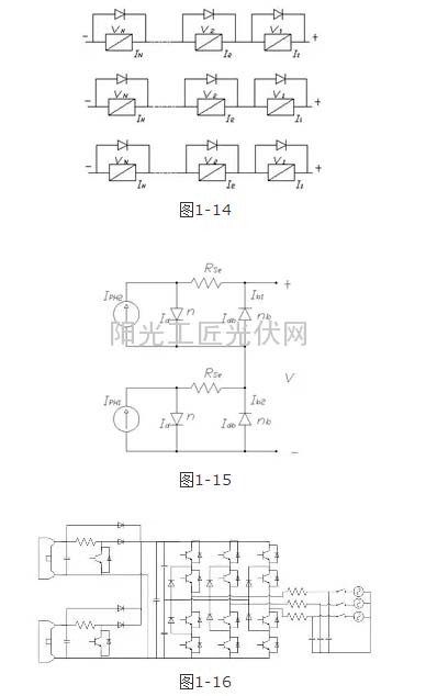
Figure 1-14 shows the equivalent circuit of the PV array. Each battery module has a bypass diode in parallel. If the component is blocked, the diode conducts. Obstructed components are bypassed so as not to affect the operation of other battery components. If a centralized inverter is used, the DC current is collected at the DC side of the inverter through the combiner box and the DC distribution cabinet. According to a conventional design, each 500 Kw centralized inverter will connect 112 strings of battery strings in parallel, and each string will be connected in series by 18-20 battery modules. Since the individual differences between the components cause differences in voltage and current between the strings, and because of the excessive number of strings in parallel, this results in coupling of voltages of different sizes, reducing the efficiency of the entire photovoltaic array.
For large ground stations, if there is no serious obstruction, power loss due to voltage mismatch is small. However, for distributed power plants, centralized inverters are not suitable if the environment is complex. A string inverter with multiple MPPTs should be used.
The string inverters have 2-3 MPPTs, which can decouple the voltage differences due to occlusions or component differences (Figure 1-16). In this way, the occluding component and the normal working component do not affect each other, and the power is fully utilized. Due to this feature of string inverters, this section only examines the case where one string is occluded.
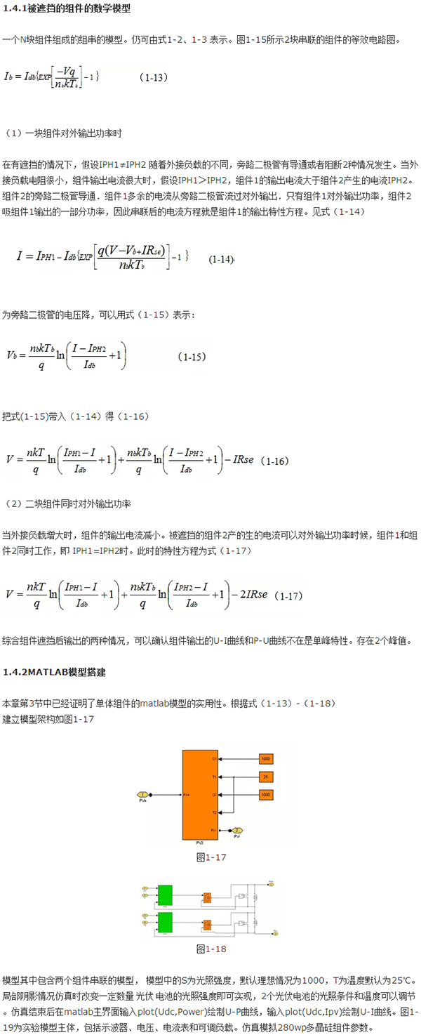
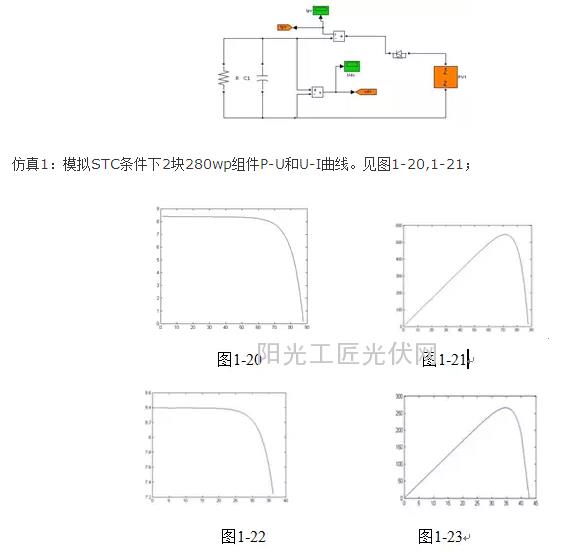
Simulation 2: Load (5Ω) under high current conditions, 2 blocks of 280wp (500W/M2) PU and UI curves when a component is blocked. See Figure 1-21, Figure 1-22. When the load is small, the output current of the module is large. Causes the bypass diode to conduct and the blocked component is bypassed. The output characteristics of the components did not change significantly, consistent with the derivation of the mathematical model. See Figure 1-22, 1-23;
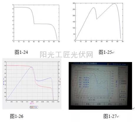
Simulation 3: Load (50Ω) under low current conditions, 2 blocks of 280wp (500W/M2) PU and UI curves when a component is blocked. See Figure 1-21, Figure 1-22. When the load is large, the output current of the module is small. The output characteristics of the bypass diode with no conduction component comply with the double-peak characteristic, which is consistent with the derivation of the mathematical model. See Figures 1-24, 1-25. The knee and double peak curves are also basically in line with the curve measured by the FLUKE-IV test instrument. Figure 1-26, 1-27
1.4.3 Multi-component modules MATLAB simulation in a complex environment
As shown in Figure 1-28, 10 battery packs (4 PV modules and PV1 modules and 2 PV2 modules) are covered by complex objects. The local temperature reaches 65 degrees Celsius. With an average irradiance of 800 W/M2, after partial shielding, the irradiance of the four battery modules was reduced to 200 W/M2, and one block was reduced to 500 W/M2.

After the simulation, Figure 1-29 and Figure 1-30 are obtained because there are 3 irradiance variables and 1 temperature variable. The UI curve shows three distinct local knee points. There are 3 local peak power points in the PU graph. Basically consistent with the theoretical derivation in the literature.
From the simulation results, it can be seen that the global maximum power is 0.88 KW. Without blocking, 800 W/M2, the theoretical maximum power of 10 280 Wp at 25° C. should be 2.25 KW. The calculated power loss is 61%. This simulation result accords with the actual situation of the project.
Summary: This chapter first analyzed the principle of the hot-spot effect, and from the perspective of the principle to explain the hot spot effect and the harm. And pointed out that only by stepping up inspections can the hot spot effect be avoided. Secondly, the engineering model of the battery module was deduced and the reliability of the engineering model was verified. Finally, the mathematical model of the battery assembly under complicated environment was deduced, and the MATLAB simulation was carried out and the results were accorded with the actual project. The engineering model can simulate component output characteristics in a complex environment. In some cases it is more convenient to use than PVSYST software.
[Safety and Ultra Lightweight]-- NO overheating after using for hours. 45 degree tilting head reduces neck fatigue. Adjustable Strap makes your head get the best comfortable condition.
[Hands-Free Lighting]-- When your task requires both hands and a bright light with a wide beam, reach for the soft digits Headlamp. It produces 300-800 lumens of different light mode to as far as 200--500 meters, with high performance led Bulbs.
[Rechargeable and Waterproof]-- Compact and powerful USB rechargeable battery provides for 6 hours using time. There is no need to change batteries. It is very convenient for you to just charge it with the USB cable. IPX6 water resistant grade, it's safe to use even when it's raining.
[8 Modes&Motion Sense Function]-- Soft Digits Headlamp has 8 modes of lighting. You get the exact level of brightness(medium/high/flash) on main light and the side light. The motion detection provides you the convenience you need for any use in the dark. Easily change between modes.
Led Head Lamp,Cob Led Headlamp,Led Head Light,Led Headlight Flashlight
Ningbo Wason Lighting Technology Co.,Ltd , https://www.nbwasonled.com
