Extrusion Die CAD System under SolidWorks Platform
SolidWorks software uses feature-based modeling technology and all-related technology of the design process. It is the leading and mainstream 3D CAD software. It has many functions such as configuration management, collaborative work, part modeling, assembly design, fully related engineering drawings, sheet metal design, finite element analysis and dynamic simulation. It is widely used in machinery manufacturing. The software provides users with a powerful API interface, and has a macro recording function, so it can be easily developed for secondary development. This article describes a set of extrusion die CAD system developed with SolidWorks software as a platform.
Based on the SolidWorks platform, the extrusion die CAD system stores a large amount of expert knowledge and design experience in the mold structure and part model. By selecting the structural shape of different mold components, the optimized design of the extrusion die is achieved. In addition, it can also realize the automatic assembly of the extrusion die by using the assembly form and assembly relationship between the mold parts, and generate the mold part drawing and the assembly drawing, thereby improving the intelligence of the extrusion die design and reducing the designer's Workload, and ensure the quality of the design, speed up the design.
The system uses VisualBasic as a development tool, using VB's object-oriented programming language, modularization and component sharing technology to establish the user interface and program code of the extrusion die CAD system; using SolidWorks to build the model of each part of the mold; The API interface function provided by SolidWorks is redeveloped to realize the call to the model library; and the parameterized driving of the part model is realized by using ADO database access technology, and finally the mold part drawing and the mold assembly drawing are generated.

Figure 1 extrusion die CAD system structure
First, the system design process
1. System functions and applications
First select the appropriate mold base, then select the type of extrusion, including positive extrusion, reverse extrusion, composite extrusion and squeezing. In different extrusion types, the structural shape of the different parts of the die, the die, the ejection, the pre-stress and the material are provided. After the user selects, a complete extrusion die assembly structure can be formed, and then a single The design of the mold parts. The user can change the parameter size of the mold part in the mold design dialog box to meet the actual needs, and can also modify the drawing of the mold part to achieve the most satisfactory results. Finally, the system automatically assembles all the designed mold parts according to the predetermined assembly relationship to generate the total assembly drawing.
2. Functional modules and design flow
The CAD system structure of the extrusion die consists of four modules, as shown in Figure 1.
(1) Formwork selection module
Many different types of formwork structures are stored in the system formwork library. By selecting different formwork names, the model picture of the formwork will appear on the right side of the structure selection dialog box. Select the main part name of the mold base, you can call up the model picture and parameter information of the part, and select the 3D map button and the engineering drawing button to open the corresponding SolidWorks model file and drawing file respectively, as shown in Figure 2.
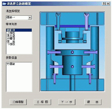
Figure 2 mold frame selection interface
(2) Extrusion type selection module
Extrusion types include positive extrusion, reverse extrusion, and composite extrusion. The extrusion type is determined by selecting the button on the left. The schematic diagram of the type and the extrusion type are shown on the right, as shown in Figure 3.
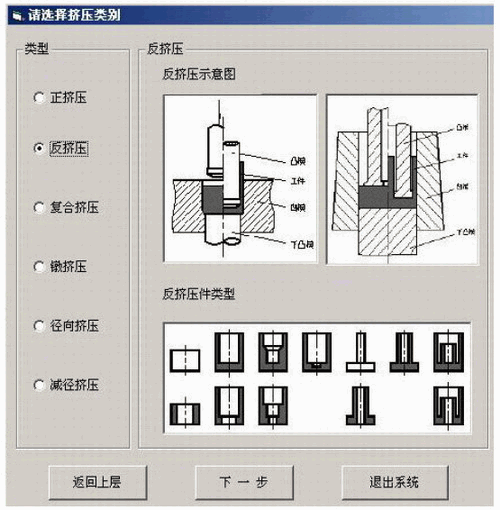
Figure 3 extrusion type selection interface
(3) Mold component structure selection module
The mold components can be divided into a punch module, a die module, an ejection component, a prestressing component, and a material component. The system establishes a mold component library for the user to select and use. In this module, the user can select any shape of different component structure. Click the zoom component button to view the detailed description and use of the structure. Click other component buttons to select other components, as shown in Figure 4.
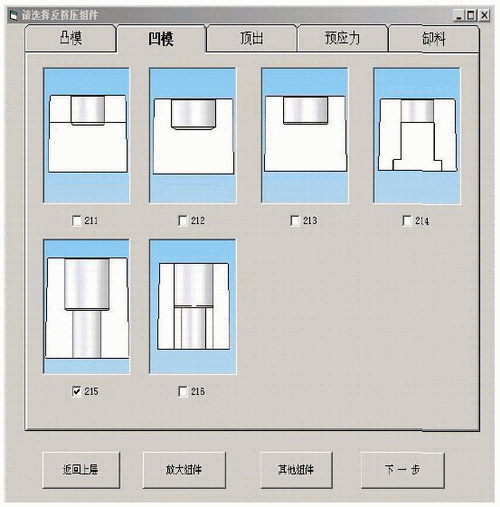
Figure 4 mold component selection interface
(4) Assembly structure confirmation module
By selecting the component structure of each part of the mold in the previous step, the system will output the assembled assembly structure diagram according to the assembly relationship and let the user confirm it. If the user feels unsatisfactory, he can return to the upper layer button to reselect each component structure. If the selected parts of the mold cannot form a set of assembly drawings, a prompt box will pop up to prompt the user to return to reselection. After confirming, the parts list of the assembly structure will appear on the right side. The mold part design module will appear by clicking the different part name buttons, as shown in Figure 5.
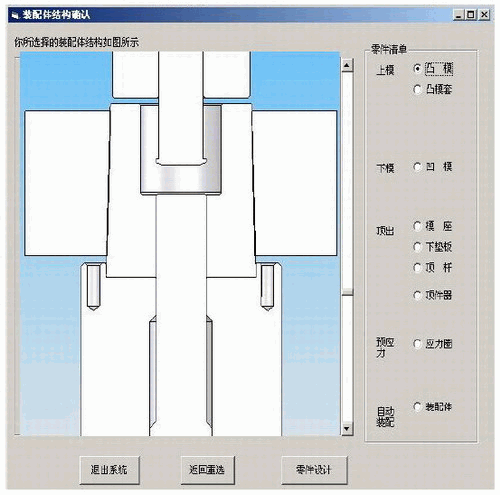
Figure 5 assembly confirmation interface
(5) Mold part design module
The system has created a database of dimensions for different mold parts. The dimensions and tolerances of the parts can be modified in the Dimension Properties dialog box. The size and tolerance of the SolidWorks model of the part will be updated in real time after the Modify button is selected. In the Annotation Properties dialog box, you can enter additional property information for the part so that it is displayed in the title bar of the part drawing. When the user is satisfied, the save button can be selected to save the model file, as shown in Figure 6.
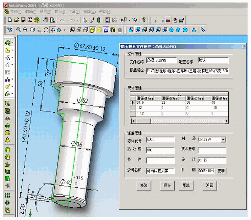
Figure 6 mold part design interface
(6) Drawing editing module
If the information on the drawing is not accurate, complete and standardized, the user can edit and modify the drawing through this module, and select the save button to realize the automatic saving of the drawing, as shown in Figure 7.
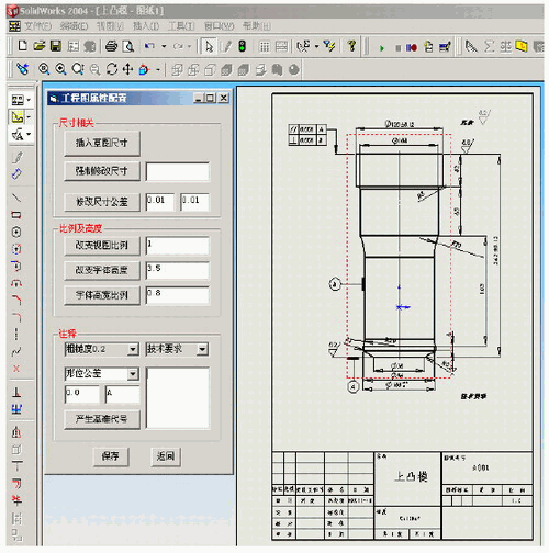
Figure 7 drawing editing interface
(7) Automatic assembly module
The system automatically assembles the various mold parts designed according to the predetermined assembly structure and assembly relationship. The mold assembly and assembly drawings of the system output are shown in Figures 8 and 9.
The main function of the system has been completed at this time, and the system can be used to promote efficient and rapid design of extrusion dies, and has been fully tested in production practice. It turns out that this system works very efficiently and works.

Figure 8 system output assembly model
Second, the system mold part design module part of the source program
In view of the large source program of this system, this paper only gives the source program of the system mold part design module.
DimssAsString
DimboolstatusAsBoolean
Ss=App.Path&"Graphics Library 3D"
SetswApp=CreateObject("SldWorks.Application")
swApp.Visible=True
'Invoke SolidWorks program SetPart=swApp.OpenDoc6(ss& "anti-squeeze 6 punch. SLDPRT", 1,0,"", longstatus, longwarnings)
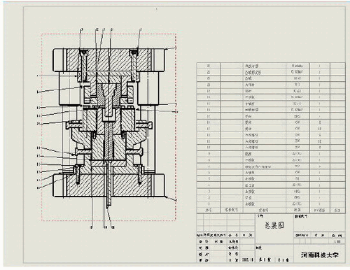
Figure 9 system output drawing
SetPart=swApp.ActiveDoc
Boolstatus=Part.Extension.SelectByID("Annotation", "DCABINET", 0,0,0, False, 0, Nothing)
'Open the corresponding model file DimrsAsADODB.Recordset
DimconnAsADODB.Connection
'Define ADO object variable ss=App.Path&"database"
Setconn=NewADODB.Connection
conn.ConnectionString="Provider=Microsoft.Jet.OLEDB.4.0;"&"PersistSecurityInfo=False;"&"Mode=read;"&"DataSource="&ss&"Mold Part Library.mdb;"
c
onn.Open
'Create an ADO connection, open the database newTableName=Str(2011)
Adodc1.RecordSource=newTableName
Adodc1.Refresh
SetDataGrid1.DataSource=Adodc1
'Open the record set, read the mold part model DataGrid1.Row=0
Fori=1ToDataGrid1.Columns.Count1
D(i)=DataGrid1.Columns(i).Value
Next
DataGrid1.Row=1
Fori=1ToDataGrid1.Columns.Count1
tolMax(i)=DataGrid1.Columns(i).Value
Next
DataGrid1.Row=2
Fori=1ToDataGrid1.Columns.Count1
tolMin(i)=DataGrid1.Columns(i).Value
Next
'Save mold part size values ​​and tolerance values ​​Boolstatus=Part.Extension.SelectByID("D1@sketch 1@emboss.SLDPRT",
"DIMENSION", 0,0,0,False,0,Nothing)
Part.Parameter("D1@sketch 1").SystemValue=D(1)/1000
Retval=Part.Parameter("D1@sketch 1").SetToleranceValues(tolMin(1)/1000, tolMax(1)/1000)
'Drive mold part size and tolerance
Third, the conclusion
Based on the SolidWorks platform, the extrusion die CAD system integrates a large number of extrusion die design materials and expert experience to form a mold design knowledge base, which provides a complete computer-aided design method for the mold design of typical extruded parts, even some lack of experience. The technicians can also use the system to complete the design of the extrusion die, which is beneficial to the promotion and application of the extrusion technology. At the same time, the system is also the development and practice of SolidWorks professional application, and it has important reference significance for the secondary development of other professional SolidWorks localization specialization. In order to make the system more complete, the mold strength check section is currently being supplemented.
Welded Wire Mesh,Metal Wire Mesh,Welded Wire Fencing,Industrial Metal Welded Wire
Shenzhou City Hongda Hardware Products Co.,Ltd , https://www.hdpvcwire.com