
Many aspects of the current application to image transmission technology, below to explain some of the problems related to wireless image transmission technology, I hope to help you.
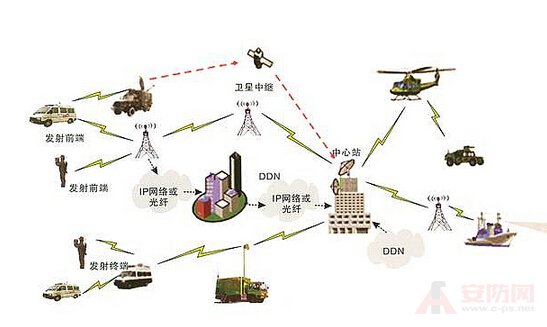
In an infrared image transmission system, there is a multi-channel communication condition, and infrared images and other information need to be transmitted back to the accusation platform through the air channel for battlefield state evaluation, target selection, and control command transmission. In the wartime wireless channel, there are always various effects such as noise, interference, multipath fading, etc., which requires the transmission system design to adopt effective data compression method to reduce the transmission rate and save the transmission channel bandwidth as much as possible. At the same time, it is necessary to introduce an error control method to resist the interference of channel noise.
This paper considers the comprehensive requirements of the system: system capacity, working distance, transmission and reception delay and algorithm implementation complexity. It adopts 8 times image compression, RS coding and interleaving to design the wireless link, and uses large-scale FPGA to complete the transmission. The algorithm implementation of the end and the receiving end, and verify that the design indicators meet the system requirements through experiments.
1 wireless channel image transmission system design
1.1 System characteristics Limited system capacity In the actual use environment, both the image sending end and the receiving end are in the air platform. Considering that there are multiple data stream communication in the system, the actual bandwidth of the image is too large, which affects the whole system capacity on the one hand, and brings There are many problems at the receiving end. In order to meet the actual engineering application, the bandwidth of each group of channels must be controlled. Therefore, the image needs to be compressed and transmitted.
Real-time performance Due to the high real-time requirements of image transmission and reception, and the limited use volume, the selected image compression and decompression algorithms must be efficient and easy to implement, and the delay is small.
High-fidelity image display Because the receiver needs to distinguish the image to make the correct choice, the image compression algorithm must use high-fidelity compression algorithm.
The interference channel environment usage environment is a complex electromagnetic environment during wartime, and there are various noises, sudden interferences, and random interferences in the channel.
1.2 System Solution Due to system capacity requirements, the frequency division system is used to complete the simultaneous operation of multiple channels, and the infrared images are compressed and transmitted to reduce the bandwidth used by each channel.
1.2.1 Transmitter design The transmitter consists of three parts: integrated baseband, transmitter and antenna. The integrated baseband is a key component, completes the acquisition, compression, encoding and interleaving of image data, completes the collection and encoding of the state data, completes the framing output of the transmitted data and the transmission control of the transmitted signal. Considering power consumption, size, and actual resource consumption, choose a large-scale FPGA to complete all signal processing.
1.2.2 Receiver Design The receiver consists of four parts: the receiving antenna, the signal processor, the receiving and processing component, the receiving processing component, the receiving of the data, the saving, the image data extraction, the decompression and display, and the extraction and display of the status data. The decompression is implemented by software, and the decompression software is embedded in the receiving software of the receiving end of the accusation platform, and the decoding and real-time display of the compressed image are completed while receiving the signal.
1.3 key technologies
1.3.1 Antenna design Because the transmitting end equipment is located on the missile and the receiving end equipment is located on the aircraft, there is a problem of the transmitting and receiving antenna mismatch. In the design, the receiving end antenna adopts a circular polarization form, and the transmitting end antenna adopts a pair of vertically distributed line poles. The antenna is designed to minimize polarization loss and facilitate reception at the receiving end. At the same time, considering the anti-interference problem during communication, the antenna of the transmitting end adopts a backward antenna pattern form, and in order to increase the anti-interference, the antenna of the transmitting end is required to have a certain gain. Figure 2 is a simulation diagram of the transmitting antenna.
1.3.2 Source Channel Joint Codec Technology Since the image format of the infrared seeker is not a standard video image format, the ordinary video image compression standard is not applicable; the image of the infrared seeker has the characteristics that the target shape changes relatively fast. The interframe compression method is also not applicable. Considering the particularity of the application environment, the compression algorithm must have simple hardware implementation, small size and power consumption. Considering the actual use environment, the compression and decompression algorithm must also have real-time performance. Therefore, the multi-resolution resampling image compression algorithm is used to compress the image data.
If the receiving end decodes the RS code using software, it will cause a large delay. Therefore, the hardware decomposes the image data, decodes and decodes the state data, and uses software to decompress the image data and display the image.
1.3.3 Selection and design of the signal processing platform At the beginning of the design, the signal processing platform of the transmitting end and the receiving end must be selected.
2 Verification Because the actual maximum spatial transmission delay can be calculated, the attenuator is used to directly connect the transmitting end and the receiving end, and directly test the signal difference between the transmitting end and the receiving end of the image data to detect the system time. Delay.
In the outdoor verification test, the receiving antenna is received by two antennas with a gain of 17 dB, and the diversity is selected into a receiver, and an attenuator is used at the front end of the transmitting system antenna.
3 Conclusion For the system requirements, multi-channel transmission is used to complete the multi-channel coexistence problem. By scientifically assigning system parameters, the transceiver antenna type is reasonably selected, and multi-resolution resampled image compression plus RS coding plus interleaved source channel joint coding is adopted. Successfully solve the problem of image transmission under the interference channel. At present, the action distance and delay test meet the system requirements, verify the rationality of the design, and provide a useful reference for the design of other image transmission systems.
Brass knurled thread insert Made of brass material, good thermal conductivity and heat resistance.
Widely Used On the Injection molding for Tightly Fixing.
Brass knurled Can be installed by ultrasonic or heat into thread tapered hole, or molded in during injection.
We are manufacturer of Insert Nut in China, if you want to buy Embedment Insert Nut,Brass Threaded Knurled Insert,Insert Thread Nuts please contact us.
knurled insert nut,threaded insert nut,wood insert nut,brass insert nut,furniture insert nut
Shenzhen Lanejoy Technology Co.,LTD , https://www.grill-grid.com