ZTE's blade Blade series has created a sales miracle at home and abroad. It is a mobile phone that I like very much. Through the 3D efficient 3D CAD/CAM function of Zhongwang 3D, ZTE N880 realistic 3D CAD modeling can be realized. At the same time, this 3D CAD tutorial step is also relatively simple, allowing you to quickly design a beautiful mobile phone 3D CAD model.

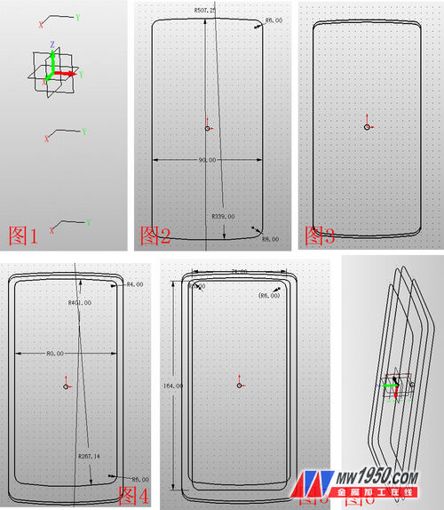
1. Create three XY datums, offset by -5, -13, and 5, and name them as datum 1, 2, and 3. As shown in Figure 1, insert sketches in XY plane, datum 1, 2, and 3, respectively. The graphs shown in Figures 2, 3, 4, and 5 (where the graph of Figure 3 coincides with the graph of Figure 2, moved down 2CM) are named as sketches 1, 2, 3, and 4, respectively, and the effect diagram is shown in Figure 6.
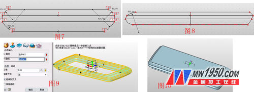
2. Insert sketches 5 and 6 on the XZ and YZ planes respectively, connect the reference points in the manner shown in Figures 7 and 8, and set the four curves of the two sketches as a curve list, named as curves 1, 2, respectively. 3, 4 (Note: For a sketch to be used separately, the curves must first be set to a list of curves, otherwise it can not be alone, there are many such cases behind). Click U/V surface, U curve select sketch 4, 1, 2, 3, V curve select curve 1, 3, 2, 4, as shown in Figure 9, click N edge surface, repair the upper and lower sides, the effect is as Figure 10.
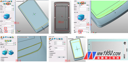
3. Click the stretch-subtraction operation, and the contour is the surface shown in Figure 11. Note that the offset term is “thickeningâ€, and the offsets 1 and 2 are 0 and 0.2 respectively. This step forms the screen between the mobile phone and the shell. Gap. Then insert sketch 7 on this side, draw a rectangle, and draw an arc below the rectangle, as shown in Figure 12. Click the stretch-subtract operation, the contour selects the arc, and pay attention to the offset item, select "shrink/expand", and the offset is 0.1. As shown in Figure 13, the edge is chamfered, as shown in Figure 14. Click on the surface--curve segmentation, and the face and curve respectively select the highlights shown in Figure 15. The purpose of this is to split the faces to facilitate the subsequent step of coloring. Insert the sketch 8 on the reference surface 4, and draw the icon shown in Figure 16. Note that the text part needs to use the "explosion" in the editing to make the text into an editable curve, and perform the surface segmentation according to the above steps. Ibid.
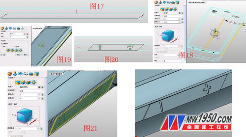
4. Insert sketch 9 on the YX surface, draw the graph shown in Figure 17, and stretch the sketch 9. The parameters are shown in Figure 18. Click on the mirror to mirror the stretched shape with the YZ surface, as shown in Figure 19. Insert the sketch 10 again on the YZ plane, draw the graph shown in Figure 20, and then add and subtract the diamond border and the "+" and "-" in the sketch. The effect is shown in Figures 21 and 22.
5. Insert the sketch 11 on the XZ plane, draw the graph shown in Figure 23, and use the stretch-plus operation, sketch 11, and the effect is shown in Figure 24. In the XY plane illustration sketch 12, draw a circular arc along the reference curve, as shown in Figure 25, click the stretch--minus operation, stretch the sketch 12, the parameters are shown in Figure 26, and the effect is shown in Figure 27.

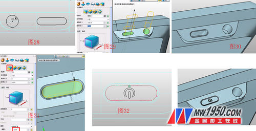
6. In the XZ face illustration sketch 13, draw the figure shown in Figure 28, point stretch - minus, stretch the sketch 13, and round the edge of the groove  Processing, as shown in Figures 29 and 30. Click on the stretch--base, select the face at the bottom of the slot to stretch, as shown in Figure 31, insert the sketch 14 on the XZ plane, draw the graph shown in Figure 32, and click on the stretch--decrement to stretch the sketch 14, the effect See Figure 33.
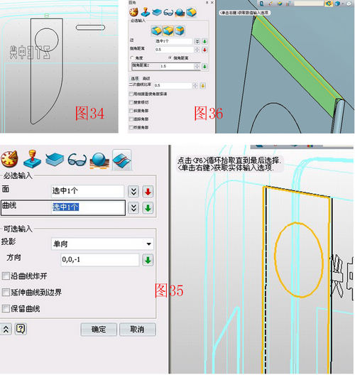
7. In the XY plane illustration sketch 15, draw the graph shown in Figure 34 and stretch the knife frame. Use the surface segmentation function to divide the stretched blade surface with a circle in the sketch for easy coloring. The parameters are shown in Figure 35. Note the selection of the projection direction. The rounded corners of the joined blade and the surface are angled, and the angle shown in Fig. 36 is inverted, and the parameters are as shown in Fig. 36.
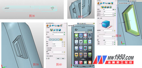
8. Insert the sketch 16 on the YZ plane, draw the graph shown in Figure 36, and use the stretch--minus operation to stretch the sketch 16 to both sides. The effect is shown in Figure 37, which is the talk hole and the USB jack. Click on the stretch--base and the outline selects the bottom surface of the USB hole. The parameters are shown in Figure 38. Click on the shape - hexahedron and select the appropriate part to draw the box, as shown in Figure 39. In order to increase the realistic degree of the model, download the N880 menu screen on the network, and use the visual style-texture map to place the menu screen in the appropriate part, as shown in Figure 40.
Finally, using the visual style-surface properties, the beautiful n880 3D CAD modeling is completed on the various colors of the mobile phone (the effect picture is as follows). Interested friends, also draw your own mobile phone 3D CAD model! Download the 3D (http://) for free now and get the latest 3D CAD/CAM tutorial! The 3D CAD drawings of this tutorial can be downloaded from the 3D Exchange Zone of the Zhongwang Technology Community (http://). As a "three-dimensional CAD material for learning", you can earn your own resource library.

Digital Tape Measure,Laser Measure Tapes,Laser Digital Measure Tape,Digital Display Laser Measure Tapes
Shangqiu Hengli Measuring Tools Co.,Ltd , https://www.jjmtools.com
