
3.2 Assembly design
Use the Add Existing Component, Create New Component, Reposition Component, Mate Component (Mate, Align, Parallel, Center, Distance, Tangent) commands to complete the assembly of all components by using the Assemblies option on the Application drop-down list. The figure is shown in Figure 2. Gap and interference checks are performed by selecting Assemblies? Components? Check Clearances or the Check Clearances icon on the assembly toolbar. Finally, the product assembly diagram is artistically rendered, and its rendering effect is shown in Figure 3.
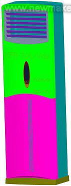
Figure 2 cabinet interior components

Figure 3 renderings of cabinet interior components
4, UG modeling experience summary
(1) Before modeling, the order of model establishment should be considered in general, especially for complex models (such as upper and lower panels of cabinets, upper and lower casings, etc.), which should be considered comprehensively. What, what to do, what to do, which has a very important impact on the completion of the post-order work;
(2) Before making important steps, carefully check the dimensions to prevent errors. For example, the “shelling†operation of the upper panel makes the inner cavity. If a part of the size is missing or misread, after doing the “shelling†operation, the work done after it may be caused by the omission. All scrapped, starting from the beginning, wasting time and affecting the progress;
(3) The modeling process should try to avoid creating "no parameters" entities, otherwise it will cause great trouble for later size changes. The operations that produce "parameterless" entities are: "Copy" operation in "Transform", "Mirror" operation of "Pattern", and "cut" operation for an entity. . The above operations should be avoided as much as possible. The first and second cases should be done with the same new entity as much as possible, or try to use the "rectangular array" and "circumferential array" in the "array". In the third case, try to use " Cut off" instead of "cut off" operation, to retain parameters can be compiled;
(4) For complex models, 3D solid modeling should be combined with the process of generating 2D graphs. In the size that is difficult to check in space, the two-dimensional map can be more accurately checked, and the generated two-dimensional map can be used to check whether the solid modeling is correct or not, and the existing problems can be found in time;
(5) It is recommended that the parameters should be checked in time after a series of entities have been made. It is best to have the product proofreader assist in checking the dimensions after a certain period of time, in order to find out the problems in time to avoid corrections and delays;
(6) Do more backups for complex parts, and save a new document at a certain stage to recall the nearest adjacent file when the file is lost or damaged due to operational errors. Do not use a document from the beginning to the end of a complex part, because when doing some operations to produce a "no parameter" entity, after saving, you can no longer return to the original fully parameterized entity, this step is irreversible. Therefore, complex parts should be backed up more frequently, and then the previously used backups will be deleted after successful completion, thus avoiding many problems. In addition, diligent backup and diligent storage are also beneficial. When there is an abnormal situation such as a crash or an erroneous operation, you can immediately re-adjust it and do it again.
Previous Next
Main products: T Head Bplts, Stud Bolts, Stud Bolts, CNC Milling Screws, Shoulder Screws, Special Pins,etc.
Our company is specializing in providing solutions to tough problems of fasteners for customers.
Stud Rod Screws,Double Thread Screw,Non Standard Fanstener,Hollow Bolt Nut Washers
Suzhou Gubao Screws Co.,Ltd. , https://www.gbscrewes.com